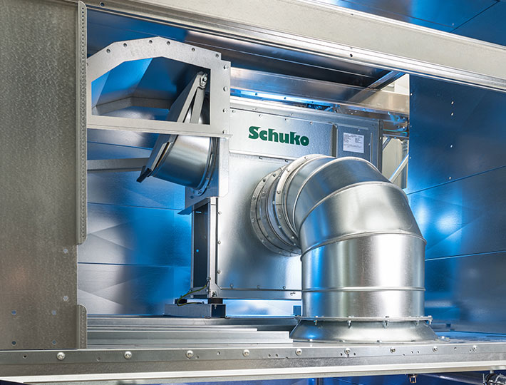
The heart of our extraction systems
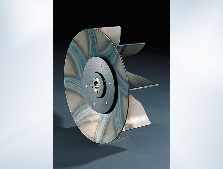
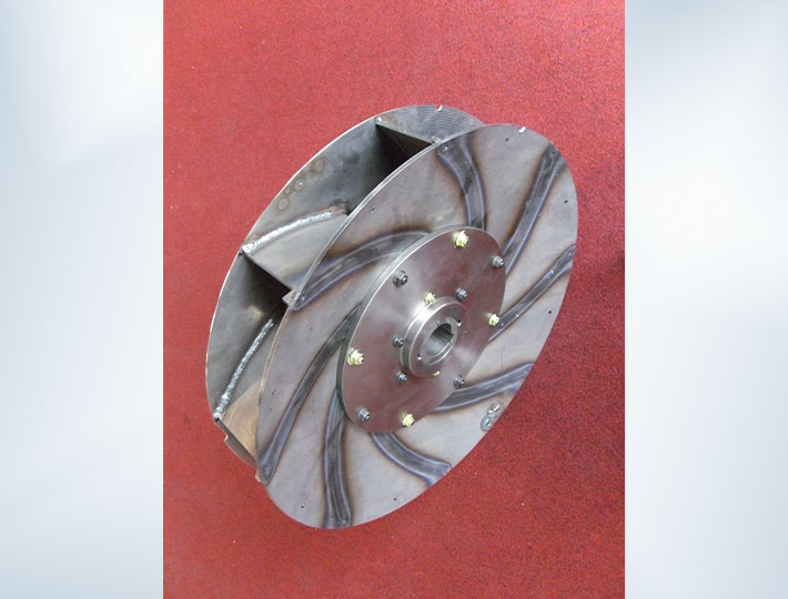
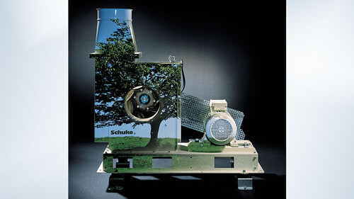
- Welded industrial radial fans
- Particularly suitable for pneumatic conveyance of dust and chips
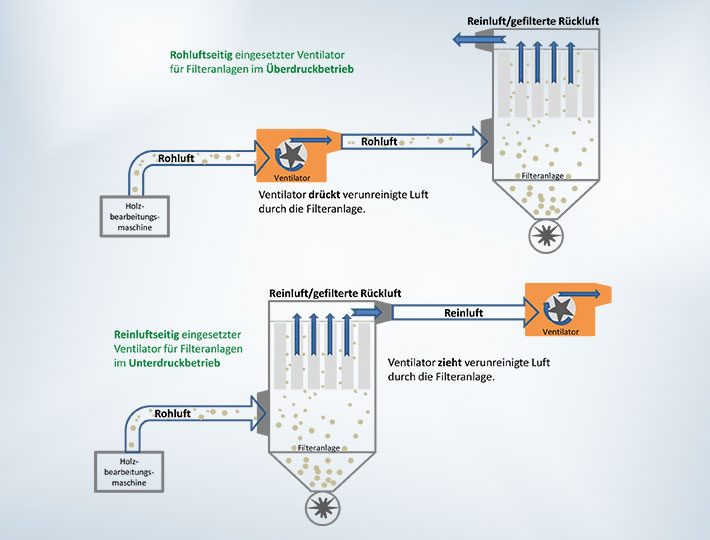
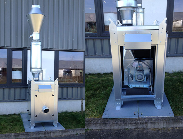
- Pressure-tight welded housing for use with extraction on the dirty air or purified air side
- Noise-reduced version available
- Highly effective impellers developed and produced in-house
- Made in Germany with German motors
Questions
on this product?
Description
As the powerhouse of an extraction system, the fans dictate the system’s effectiveness and operating costs. Schuko fans are particularly suitable for pneumatic conveyance of dust and chips, e.g. from woodworking, paper conversion and plastics processing operations. In the welded industrial version, they are designed for lengthy operation, are developed in-house and are produced individually – made in Germany.
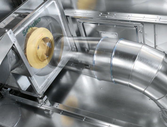
With a so-called radial fan a larger increase in pressure is generated with same amount of air. Air is sucked in parallel to the drive axis of the radial fan and returned by the rotation of the impeller by 90° and is blown out radially.
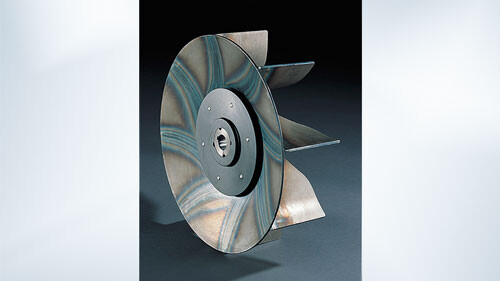
Impellers from our in-house production facilities have extremely high efficiencies which lead to optimal energy use.
There are two different types of fan impellers:
- Open impellers for materials handling or fans used on the dirty air side
- Efficiency ranges from 50% to 62%
- Shrouded impellers for dust handling or fans installed on the clean air side
- Efficiency ranges from 78% to 82%
Other advantages
- In-house production makes individual adaptations possible for optimally coordinating the fan with the targeted application and extraction task.
- Fast manufacturing and delivery lead times resulting from the intelligent system design ensure prompt system availability.
- Different housing positions are available.
- The pressure-tight welded housings are suitable for both negative and positive pressure operation of filter systems.
- Schuko fans can be used on the clean or dirty air side through selection of the appropriate impeller.
- Available in lightweight and welded industrial versions:
- weight and material cost savings in clean air handling applications.
- extremely robust and long-lasting for trouble-free extraction in materials handling applications. - Available in galvanised and painted versions.
- Statically and dynamically balanced steel impellers according to ISO 14694 for wear-resistant and vibration-free operation.
- Reinforced fan impellers provide for long life and trouble-free extraction in heavy-duty materials handling applications.
- Easy conversion and thus no need to buy a new fan when performance data change.
- Noise-reduced fans inside an acoustic enclosure are especially quiet. Further noise reduction solutions can be supplied upon request.
- Schuko has developed a special fan series called ‘shredding fans’ for the paper conversion industry.
- All fans are performance-tested prior to delivery so you can rest assured that the fan has the power you need for your system.
- An in-house safety test is performed on each fan at up to 2x fan speed to guarantee the safety of your fan.
Energy-saving tips for fans
The extractor fans are some of the biggest power consumers in an extraction system. For this reason it can be worthwhile to look more closely at the power consumption of the existing fans in an extraction system. Schuko fans and impellers are continuously optimised on in-house test benches to convert the electrical power as effectively as possible to air data.
Potential savings from fan impellers:
Check the running impellers for signs of wear and for changes in the blade shape. Fan impellers with plastic impeller blades should be closely examined in this context. Over the years these plastic blades erode and the efficiency decreases. Replacement with new blades or possibly even with a modern steel fan impeller with curved blades can increase the efficiency of the extractor fan by around 5% to 10% at little expense
Potential savings from shut-off gate valve:
Extraction systems are usually not designed for simultaneous extraction of dust from all machine tools. Machine tools that are not in use are hence separated from the duct system via gate elements.
Inform your employees that opened gate valves on unused machines waste energy. This process measure can noticeably lower the energy consumption without new investments. The more air a fan has to move, the higher the power consumption in amperes is.
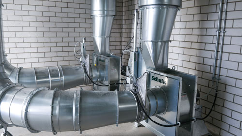
The machine tools can alternatively be retrofitted with automatic energy-saving gate valves (see photo) which are only open when the tool is in operation.
Potential savings from minimal running time:
The starting currents of fans can increase to up to five times the rated current of the drive motor. Frequent switching on and off thus unnecessarily loads the electricity mains and the drive motor. A minimum running time can be set up to avoid these start-up spikes. For more information please contact an electrician or Schuko.
Handling systems for filling of chip silos or chip containers can also be examined in this connection. Many systems are technically quite capable of storing a certain amount of material. In this case it is not necessary for handling fans to be run all day long. Cycling can be suitable here. However, the material volume must be known and must not exhibit any large spikes.
These adjustments must be made very carefully and be precisely coordinated with the system. Incorrect cycle times can cause material to accumulate in the system and clog it up. Your Schuko technical advisor will be happy to provide you with tips.
Potential savings from performance adjustment:
Performance adjustment in an extraction system is a fundamental approach to saving energy. However, overall performance capability should not be done away with in the process.
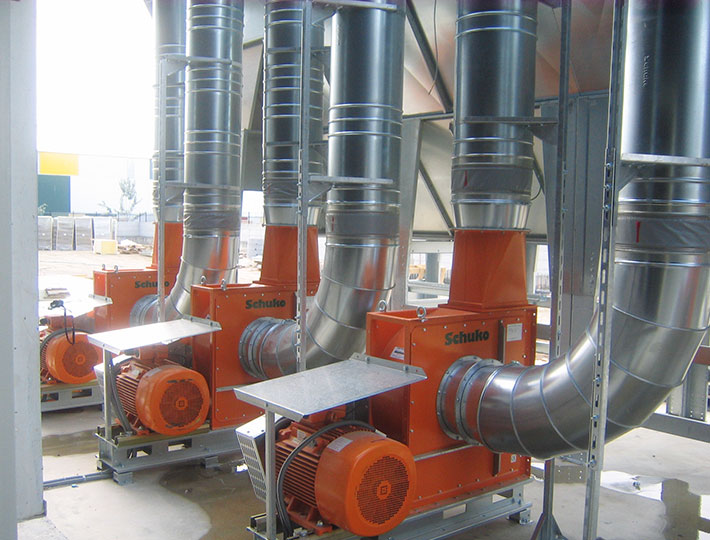
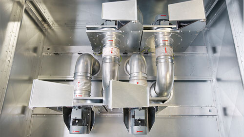
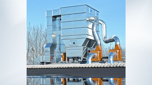
The Schuko cascade system allows the extraction system performance to be regulated and adapted precisely according to the given air requirements. It uses several individual fans which can be switched on or off depending on requirements. Thus the maximum pressure increase can be generated even with a low airflow.
Notes regarding replacement deliveries:
Please note that after 16 June 2011 in accordance with the MEPS (European Minimum Energy Performance Standard) motor manufacturers will only be permitted to place drive motors corresponding to an efficiency class on the market. Motors which are still in stock at suppliers’ or intermediate agents’ premises are considered to have been placed on the market and thus may also be sold to end consumers. Hence for replacement deliveries ensure adherence to the currently prescribed efficiency class (as of 2017: IE3 for powers of 0.75 kW to 375 kW or IE2 motor with frequency converter).
Planning tips for new acquisitions:
As described above, the efficiencies of open and shrouded fan impellers differ considerably. If the fans are used in your planned new system on the clean air side, then shrouded impellers with a high efficiency are the obvious choice.
However, following more careful consideration, it is possible for fans with shrouded impellers to be used for dirty air-side extraction units primarily for machine tools that generate fine materials (excluding planing swarf), for example, for extraction of dust from CNC machines or grinding machines.
Check your systems regularly and make sure that new acquisitions are at the state of the art to avoid unnecessary power consumption and the associated costs.
Pipe cross sections and airflows
Determination of pipe cross section (m²) and airflow (m³/h)
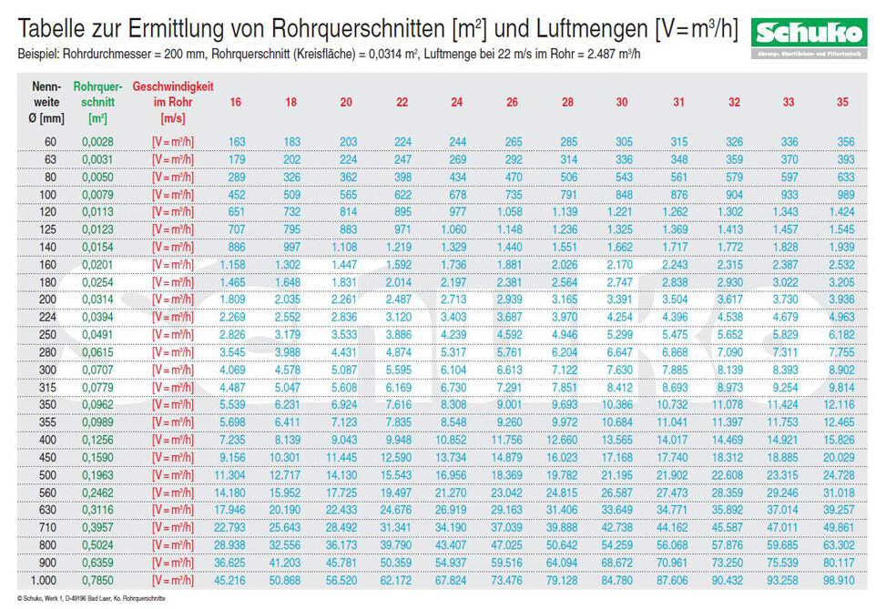
Schuko prepared a pipe cross section table (see below, also available as a PDF for download) for simple determination of pipe cross sections and airflows. The following application examples illustrate the handling:
- Example 1:
The airflow needed for extraction of dust from a machine tool with a connection port size of 200 mm is sought. The manufacturer prescribes an air speed of 22 m/s in the extraction nozzle.
Go to the value ‘200’ in the ‘Nominal size’ column and go across to the corresponding value in the column with the header ‘22’. The air speed can be read directly: 2487 m³/h. - Example 2:
A machine with two extraction nozzles of Ø 120 mm and 80 mm (panel saw) should be connected. The diameter of the main trunk, i.e. the diameter yielded from the combination of the two machine nozzles, is sought.
Go to ‘80’ in the ‘Nominal size’ column and go across to the next column (‘Pipe cross section’). You will see the value of 0.0050. The area of the circle is hence 0.0050 m². For a diameter of 120 mm you can find the value, i.e. 0.0113 m², using the same procedure.
Now add these two circle areas together. The sum is 0.0163 m². With this result, go to the ‘Pipe cross section’ column. There is no value corresponding exactly to 0.0163. The closest value is 0.0154 for a diameter of 140 mm. The diameter of 140 mm is selected.
- Example 3:
Machine manufacturer A requires a volume flow (airflow) of 5,829 m³/h in an extraction nozzle of Ø 250 mm. You would like to know what the corresponding air speed is because machine manufacturer B requires 28 m/s in the extraction nozzle.
Go to Ø 250 mm under the ‘Nominal size’ column, move across the row to the value of 5,829 and from there up to the column header. You will see that 5,829 m³/h corresponds to an air speed of exactly 33 m/s. Machine A thus demands a higher air speed than machine B. 28 m/s in an extraction nozzle of 250 mm corresponds to 4,946 m³/h. - Example 4:
An existing machine with an extraction diameter of 250 mm should be replaced with a new machine with an extraction diameter of 300 mm. The extractor fan’s power is adapted to the new machine, but the pipe from the fan to the silo has a Ø of 250 mm and replacement with a Ø 300 mm one would be technically difficult. The air speed in the extraction nozzle should be 24 m/s, or 6,104 m³/h. How high would the corresponding air speed be for the old pipe with a diameter of 250 mm?
Go to ‘250’ in the ‘Nominal size’ column and look for the value of 6,104 in this row. You will find the value 6,182 m³/h. Now go up to the header. The air speed in the 250-mm-diameter pipe is approximately 35 m/s.
Technical data
| Series | Connection Ø mm | Motor power kW | Maximum flow rate m³/h |
|---|---|---|---|
| S – for standard machines | 120 - 500 | 1.5 - 37 | up to 21,200 |
| K – belt-driven | 250 - 560 | 7.50 - 37.00 | up to 26,500 |
| TSK – for further transport of dust and chips | 200 - 300 | 3.00 - 11.00 | up to 7,600 |
| KG – V-belt drive with base frame | 300 - 800 | 22.00 - 110.00 | up to 54,000 |
The following products might also interest you:
Questions on a particular product?
Call our product advisor on 0049 7581 4871 0 or use the form below. A Schuko employee will only visit you if you explicitly require it and have indicated this above.

